
Views: 0 Author: Site Editor Publish Time: 2026-08-01 Origin: Site


Complex tube processing—involving intersecting profiles, bevels, and multi-axis geometries—requires tolerances that traditional mechanical cutting methods cannot reliably achieve without extensive secondary operations. Manufacturers face a critical gap between advertised machine specifications and actual shop-floor performance. Misjudging a machine's true accuracy leads to high scrap rates, poor fit-up during automated welding, and unexpected downstream labor costs. Evaluating the true capabilities of a Tube Laser Cutting Machine requires moving beyond top-line marketing claims to analyze mechanical rigidity, chucking systems, thermal dynamics, and software interpolation. This guide breaks down how to assess machine accuracy for high-stakes production environments.
Baseline Tolerances: Top-tier machines can achieve cutting accuracies of ≤±0.05mm, but real-world results depend heavily on material quality, tube straightness, and thermal management.
Dedicated vs. Dual-Use: A dedicated tube laser cutting machine typically offers up to a 40% increase in single-shift throughput and superior rotational accuracy compared to flatbed lasers with tube attachments.
Speed vs. Precision Thresholds: High-speed processing (ranging from budget 600 mm/s to premium 3,500 mm/s or 120 m/min) must be balanced with axis acceleration; raw speed without dynamic vibration dampening compromises cutting tolerances.
Total Cost of Accuracy: Achieving and maintaining peak precision requires factoring in the ongoing costs of high-quality consumables, routine calibration, and advanced nesting software.
Absolute positioning accuracy refers to the machine's ability to reach an exact programmed coordinate in three-dimensional space. Repeatability measures the system's capacity to return to that exact same coordinate consistently across a production run of hundreds or thousands of parts. In complex tube fabrication, repeatability often outweighs absolute accuracy. When cutting intersecting geometries like saddle cuts, slotted joints, or coping profiles, minor deviations compound rapidly. A machine that consistently hits a slightly offset mark allows operators to adjust the global program offset. A machine with poor repeatability produces unpredictable variations, making automated robotic welding impossible and forcing manual fit-up adjustments on the assembly line.
Shop floor reality dictates that a machine must hold its zero point across multiple shifts. When you load a 24-foot stick of carbon steel, the machine indexes the material, calculates the cut paths, and begins processing. If the drive gears or servo motors suffer from backlash, the first part might measure perfectly, but the fiftieth part will drift out of tolerance. You verify repeatability by running a nest of identical parts and measuring the variance between the first, middle, and last pieces. Consistent results prove the drive system and encoders are functioning correctly under load.
Accuracy requirements and mechanical behaviors shift dramatically when transitioning from symmetric round and square tubes to open, asymmetrical profiles. Processing C-channels, angle iron, and custom aluminum extrusions introduces severe physical twisting during rotation. Unlike a closed round tube, an open profile lacks structural rigidity, causing asymmetric structural sag over long spans. Maintaining precision on these profiles requires specialized software algorithms capable of calculating constantly shifting centers of rotation. The machine must dynamically adjust the laser focal point and cutting head angle to compensate for the physical whip and deflection of the open geometry as it spins within the chucks.
Consider the mechanics of cutting a heavy-wall C-channel. The center of mass does not align with the center of rotation. As the chuck spins the material, centrifugal force pulls the heavier side outward. Without active compensation, the laser head will cut a distorted profile. Advanced controllers map this eccentric rotation and move the cutting head in real-time to maintain a consistent standoff distance. This dynamic tracking separates high-end equipment from basic rotary cutters.
| Profile Type | Structural Rigidity | Rotational Behavior | Primary Accuracy Challenge |
|---|---|---|---|
| Round Tube | High | Symmetrical, balanced | Maintaining consistent focal length on curved surfaces. |
| Square/Rectangular | High | Symmetrical, variable radius | Managing acceleration around sharp corners to prevent overburning. |
| C-Channel / Angle Iron | Low | Asymmetrical, eccentric | Compensating for shifting center of mass and physical whip. |
| Custom Extrusions | Variable | Unpredictable | Preventing chuck crush damage while maintaining firm grip. |
Laser cutting relies on intense localized heat to vaporize metal, which inherently creates a Heat-Affected Zone (HAZ) along the cut edge. Excessive heat input severely distorts thin-walled tubes, compromising the mechanical accuracy of the final cut regardless of the machine's positioning precision. Thermal expansion causes the tube to bow mid-cut, leading to dimensional drift. Success criteria for edge quality extend beyond mere dimensional numbers; they include smooth cut surfaces, the complete absence of dross, and minimal metallurgical changes. Managing the HAZ requires optimizing the laser duty cycle, pulse frequency, and assist gas pressure to ensure the cut edge remains structurally sound and ready for downstream welding without secondary grinding.
When processing thin-wall stainless steel, heat management becomes the primary factor in part accuracy. If the laser dwells too long on a corner, the material warps. The cut might be dimensionally accurate according to the encoders, but the physical part will fail a go/no-go gauge test. Operators mitigate this by using lead-ins, micro-joints, and optimized cutting sequences that distribute heat evenly across the tube rather than concentrating it in one area.
Many fabrication shops initially attempt to process tubes using rotary attachments bolted onto standard flatbed lasers. These dual-use hybrids present significant limitations regarding chuck stability, weight limits, and indexing precision over long tube lengths. The rotary axis on a flatbed is typically an afterthought, lacking the heavy-duty bearings and multi-point support systems required to keep a heavy steel tube perfectly level. As the tube extends beyond the rotary chuck, gravity induces sag, which immediately throws off the cutting geometry. These hybrid systems serve a specific purpose: they are ideal for low-volume, high-mix shops where tube cutting is an occasional requirement rather than a core competency.
The physical limitations of a hybrid system become obvious when processing anything longer than a few feet. A flatbed laser lacks the pass-through chuck design necessary to feed long stock continuously. You are restricted to cutting pre-cut lengths, which increases material waste and handling time. Furthermore, the rotary attachment often lacks the torque required to spin heavy-wall tubing rapidly, forcing the operator to reduce cutting speeds to maintain accuracy.
Operations processing structural tubing daily require the engineering advantages of dedicated systems. A true Precision Tube Laser Cutter utilizes multi-chuck designs, active tube supports, and specialized rotary axes engineered specifically to eliminate tube sag and whip. Three-chuck and four-chuck configurations allow the machine to hold the tube rigidly on both sides of the cutting head, achieving zero-tailing processing and maintaining strict tolerances across the entire length of the raw material. Dedicated systems routinely deliver a throughput advantage of up to 40% higher than hybrid machines. The ROI threshold that justifies this capital expenditure is crossed when a shop spends more than twenty hours a week struggling with manual tube coping, drilling, and fit-up rework.
Dedicated machines transform raw stock into finished components in a single operation. They handle the loading, indexing, cutting, and unloading automatically. This continuous flow eliminates the stack-up tolerances that occur when moving parts between a saw, a drill press, and a deburring station. The rigidity of a dedicated heavy-duty frame absorbs the vibrations generated by high-speed servo movements, ensuring the laser beam remains perfectly focused on the material surface.
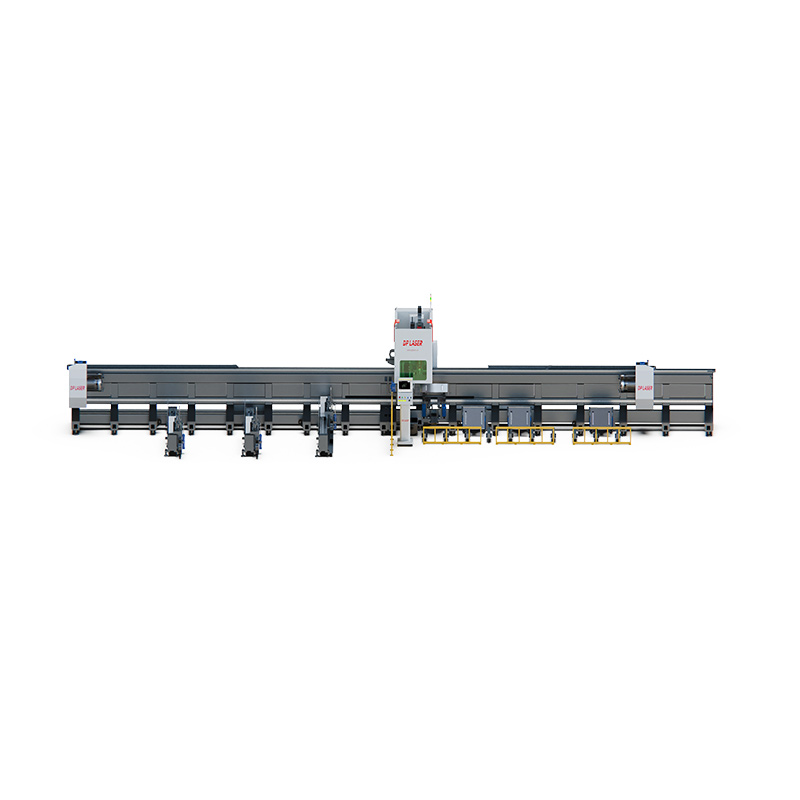
The chucking mechanism is the physical foundation of tube cutting accuracy. Pneumatic chucks offer fast clamping but often apply uniform, unyielding pressure that can crush or deform thin-walled or non-circular profiles. Servo-driven chucks provide programmable clamping pressure, allowing the machine to hold delicate aluminum extrusions firmly without altering their dimensional integrity. Maintaining alignment over 6-meter to 8-meter tube lengths requires sophisticated material handling. Floating supports dynamically rise and fall to cradle the tube as it feeds through the machine, preventing gravitational deflection. Automated loading and unloading systems further protect accuracy by eliminating the heavy impacts and misalignments caused by manual forklift loading.
A multi-chuck system provides superior control over the material. In a three-chuck setup, two chucks feed the material while the third chuck supports the cut piece. This prevents the part from dropping or shifting during the final micro-seconds of the cut, which often causes a small burr or dimensional error on lesser machines. The synchronized rotation of all chucks ensures the tube remains perfectly aligned with the cutting head, regardless of its length or weight.
Modern fiber laser technology has largely replaced legacy CO2 systems for tube processing. Fiber lasers deliver a smaller spot size, resulting in a narrower kerf and superior precision. They also safely process highly reflective materials like brass and copper, which would damage the optics of older CO2 machines. Cutting dynamics rely heavily on the correlation between wattage, traverse speed, and axis acceleration.
| System Tier | Typical Speed Class | Acceleration (G-Force) | Accuracy Impact & Best Use Case |
|---|---|---|---|
| Budget-Tier | Up to 600 mm/s | 0.8G - 1.0G | Adequate for simple cut-offs and thick walls. High vibration at top speeds reduces corner precision. |
| Mid-Range | Up to 1,200 mm/s | 1.2G - 1.5G | Balances speed and accuracy. Good for standard structural profiles and moderate production volumes. |
| Premium | Up to 3,500 mm/s (120 m/min) | 2.0G+ | Maintains strict ≤±0.05mm tolerances at extreme speeds due to heavy cast-iron frames and advanced vibration dampening. |
High G-force acceleration capability is required to maintain precision at high speeds. A machine that moves fast but accelerates slowly will round off sharp corners and overburn intricate geometries. The cutting head must reach optimal speed instantly and decelerate just as fast to maintain a uniform kerf width. This requires massive servo motors and a rigid gantry system capable of handling extreme kinetic energy without flexing.
Mechanical rigidity means nothing without advanced software interpolation. The CNC controller and CAM software translate 3D CAD models into precise machine movements, coordinating the simultaneous rotation of the chucks with the X, Y, and Z axes of the cutting head. High-end systems utilize active seam detection, using optical sensors to locate the weld seam on raw tubing and automatically rotating the profile so the seam avoids critical cutouts or bend lines. Twist compensation features use touch probes or lasers to map the physical distortion of the raw tube before cutting begins, dynamically adjusting the cutting path to correct for raw material imperfections in real-time.
When you load a bundle of square tubing, the material is rarely perfectly straight. It has camber, sweep, and twist. If the software assumes the tube is geometrically perfect, the cut features will be misaligned. Active compensation systems probe the material at multiple points along its length, creating a digital twin of the actual physical tube. The controller then morphs the cutting program to match the real-world geometry, ensuring holes and slots align perfectly during final assembly.
High-speed precision introduces hidden operational variables that impact the overall output of the machine. Nozzle wear, protective window degradation, and the consumption rates of assist gases directly influence cut quality. Nitrogen provides a clean, oxide-free cut essential for stainless steel and aluminum, but it requires high pressure and volume. Oxygen is used for thicker carbon steel but leaves an oxidized edge. Nozzle wear directly degrades cutting tolerances by altering the gas flow dynamics around the laser beam. Maintaining a machine's long-term accuracy requires automated nozzle changers and automatic beam centering calibration systems.
Operators must monitor the condition of the protective glass constantly. A single speck of spatter on the lens absorbs laser energy, causing thermal lensing. This shifts the focal point of the beam, resulting in wider kerfs, heavy dross, and lost dimensional accuracy. Implementing a strict maintenance schedule for optics and nozzles is mandatory for holding tight tolerances over long production runs.
The true value of high accuracy lies in downstream efficiency. Eliminating deburring, drilling, and manual coping stations drastically reduces part cycle times. When a tube comes off the machine ready for immediate robotic welding, the workflow transforms. A highly accurate machine shifts labor from manual fabrication and grinding to machine programming and quality assurance. Operators spend their time optimizing nests and managing material flow rather than fixing bad cuts with an angle grinder. Quantifying this value requires tracking the reduction in scrap rates and the hours saved in the welding bays due to perfect joint fit-up.
Consider a structural frame requiring dozens of intersecting saddle joints. Cutting these manually with a bandsaw and grinder takes hours and rarely results in a perfect fit. A laser cuts the exact complex geometry in seconds. The resulting joints fit together tightly, requiring less weld filler metal and reducing the heat input during welding, which minimizes final assembly distortion.
No machine, regardless of its software or mechanical design, can perfectly cut heavily bowed, twisted, or severely out-of-spec raw tubing. Mill tolerances for structural steel often allow for significant bowing over a 24-foot length. The primary mitigation strategy is establishing strict purchasing specifications for raw materials. Buy laser-quality tubing whenever possible. For unavoidable material variations, utilize machines equipped with advanced touch-probe or optical compensation systems that measure the actual tube geometry and adjust the cutting program dynamically to match the physical reality of the material.
You cannot fix bad steel with a good laser. If the wall thickness of a square tube varies by ten percent from one side to the other, the laser will cut differently on each face. Establishing a strong relationship with your steel supplier and demanding tight mill tolerances is just as important as selecting the right machine.
Transitioning to multi-axis tube processing involves a steep learning curve. 3D tube nesting software requires operators to understand spatial geometry, kerf compensation, and thermal dynamics. Proper training is non-negotiable for achieving the machine's advertised accuracy. Furthermore, the facility must meet strict prerequisites. A stable, isolated concrete foundation is required to prevent external vibration from inducing inaccuracies during high-speed cutting. Clean, dry, and oil-free compressed air is mandatory to protect sensitive optics. Climate control within the facility helps maintain the stability of the laser source and electronic components, ensuring consistent performance across varying seasonal temperatures.
Verify foundation requirements with the machine manufacturer before installation.
Install dedicated air dryers and filtration systems for the assist gas supply.
Train operators extensively on 3D CAD/CAM software and nesting optimization.
Implement a daily checklist for cleaning chuck jaws and inspecting protective optics.
Demand a live test cut using your specific raw materials and complex part files before purchasing.
Inspect the resulting test parts for HAZ, dross, and dimensional accuracy using a Coordinate Measuring Machine (CMM).
Prioritize machines with robust multi-chuck systems and active twist compensation for processing long or thin-walled tubes.
Establish strict purchasing specifications for raw materials to ensure laser-quality tubing feeds the machine.
A: The standard cutting tolerance typically ranges from ±0.05mm to ±0.1mm. This depends heavily on the machine tier, the thickness of the material being processed, and the overall length and straightness of the raw tube.
A: Yes. Modern fiber laser sources can process highly reflective materials efficiently. Unlike older CO2 technology, fiber lasers are designed to handle back-reflections without damaging the laser source or internal optics.
A: Dedicated machines offer superior rotational accuracy, active support for long tubes to prevent sagging, and up to 40% higher throughput for continuous tube processing compared to flatbed hybrids.
A: Primary culprits include raw material bowing or twisting, thermal distortion from excessive heat input, worn consumables like nozzles and protective lenses, and inadequate or uneven chuck clamping pressure.
A: Yes. Pushing a machine to its maximum traverse speed on complex geometries can induce mechanical vibration and increase dross. Speed must be optimized alongside laser frequency and duty cycle for the specific material.
A: Nitrogen is typically used for clean, oxide-free cuts on stainless steel and aluminum, allowing for immediate welding. Oxygen is used for thicker carbon steel but leaves an oxidized edge that may require cleaning.


