
Views: 0 Author: Site Editor Publish Time: 2026-07-31 Origin: Site


The transition from traditional mechanical cutting and legacy CO2 systems to solid-state fiber optics is fundamentally restructuring metal fabrication workflows and throughput expectations. Fabrication facilities face compounding bottlenecks in tube processing. Relying on sequential, disconnected operations like sawing, drilling, milling, and deburring increases labor costs, introduces mechanical stress, and degrades part accuracy. Moving raw stock from a band saw to a drill press and then to a deburring station consumes floor space and man-hours. It also multiplies the chances for human error.
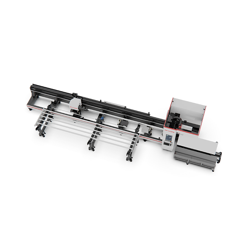
Shifting to a consolidated automated system requires evaluating how a Fiber Laser Tube Cutting Machine impacts total operational efficiency, edge quality, and long-term production stability. You replace physical blades with high-density light. This allows you to process complex geometries in a single setup. You eliminate secondary handling and reduce scrap rates. We will examine the technical advantages, operational shifts, and integration strategies necessary to leverage solid-state laser technology for high-volume tube fabrication.
Process Consolidation: Replaces multiple mechanical steps (cutting, drilling, coping, slotting) with a single, highly predictable automated setup.
Superior Energy Efficiency: Fiber technology delivers significantly higher wall-plug efficiency compared to traditional CO2 systems, drastically reducing ongoing utility costs.
Zero Mechanical Stress & Low Heat: Eliminates physical clamping deformation and minimizes thermal deformation, yielding clean, burr-free edges that bypass secondary deburring.
Before integrating advanced optical cutting systems, fabrication managers must identify the hidden inefficiencies plaguing traditional tube fabrication workflows. Conventional methods require moving raw materials across multiple discrete stations. A typical workflow involves cutting a tube to length on a band saw, moving it to a drill press for hole creation, and transferring it to a milling machine for slotting or coping. Each transfer introduces material handling delays. It increases the risk of manual measurement errors and elevates scrap rates. Physical tool wear on saw blades and drill bits leads to inconsistent cuts. This causes downstream assembly alignment issues that force welders to spend excessive time filling gaps or grinding edges.
To justify upgrading equipment, facilities must define success through measurable, objective metrics. Cycle time reduction stands as the primary indicator of efficiency. By measuring the time it takes to convert a raw tube into a fully processed, assembly-ready component, managers can accurately gauge throughput improvements. Dimensional tolerance consistency is equally important. Parts must interlock perfectly without manual rework. Material yield improvement serves as another vital metric. Advanced nesting capabilities reduce the amount of skeleton scrap left at the end of a raw tube. This maximizes the number of usable parts extracted from every stock length.
The necessity for advanced multi-axis control becomes apparent when assessing part complexity. Modern structural designs increasingly rely on intricate geometries, intersecting cuts, and variable tube profiles. Processing round, square, rectangular, and open profiles like channels or angles demands a system capable of rotating the material while simultaneously maneuvering the cutting head. Traditional mechanical tools simply cannot execute complex miter cuts or intersecting saddle joints with the speed and precision required for modern manufacturing. A consolidated optical system bypasses these limitations. It allows engineers to design superior, self-aligning joints that streamline the entire fabrication lifecycle.
Consider the daily reality on a busy shop floor. When a fabricator relies on manual layout for intersecting pipe joints, the margin for error is massive. A worker uses a wrap-around template, marks the cut line with soapstone, and attempts to follow that line with a plasma torch or grinder. The resulting fit-up is rarely perfect. Welders then spend hours grinding the bevels to achieve proper root penetration. An automated optical system eliminates this entire sequence. The machine reads the CAD file and executes the exact saddle cut with a pre-programmed bevel angle in seconds. The parts fit together with zero gap, allowing the welder to strike an arc immediately.
The fundamental physics of solid-state fiber lasers provide a distinct advantage over older technologies. A fiber laser generates its beam within an active fiber and guides it to the cutting head via a flexible transport fiber. This solid-state delivery mechanism ensures incredibly stable beam quality. The resulting laser beam features a significantly smaller spot size compared to CO2 lasers. It concentrates immense energy into a microscopic area. This high energy density vaporizes metal instantly, resulting in a remarkably narrow kerf width and exceptional dimensional accuracy.
Because the heat input is highly localized, the surrounding material experiences minimal thermal deformation. Traditional cutting methods often generate wide heat-affected zones (HAZ) that alter the metallurgical properties of the tube. This leads to warping or hardening that complicates downstream welding. The rapid processing speed and concentrated energy of a fiber laser preserve the structural integrity of the tube. It yields clean, square, and burr-free edges that completely bypass the need for secondary deburring operations.
When cutting 304 stainless steel tubing for food-grade applications, edge quality dictates project success. Mechanical saws leave jagged burrs and introduce carbon contamination if the blade was previously used on mild steel. A laser system using high-pressure nitrogen assist gas blows the molten material cleanly through the kerf. The result is a bright, oxide-free edge that requires no wire wheeling or flap disc grinding before sanitary welding.
Mechanical cutting relies on physical force. Saws, punches, and milling tools require heavy clamping systems to hold the material rigid against the extreme torque and friction of the cutting action. For thin-walled profiles or delicate structural shapes, this physical clamping frequently causes crushing, distortion, or surface marring. The sheer force of a physical blade can also introduce micro-cracking along the cut edge, compromising the fatigue resistance of the final component.
Non-contact cutting eliminates these issues entirely. The laser head hovers above the material, applying zero physical pressure to the tube. The chucks that rotate the material only need to apply enough force to secure the tube's position, not to resist the violent torque of a saw blade. This allows manufacturers to process extremely thin-walled aluminum, stainless steel, and copper profiles without fear of crushing or dimensional distortion. The final part matches the CAD model perfectly.
Traditional fabrication is plagued by physical tooling changeovers. Switching from cutting to drilling requires stopping the machine, changing the tool, adjusting the coolant, and recalibrating the zero point. A Tube Laser Cutting Machine eliminates all unnecessary mechanical movements. The laser beam acts as a universal tool. It cuts straight lines, drills microscopic holes, and carves complex slots in a single continuous sequence.
The specific 1-micron wavelength of fiber lasers is highly absorbed by metals, allowing for incredibly accelerated feed rates. When processing complex geometries such as intersecting miter cuts, keyholes, or custom slotting, the machine's multi-axis interpolation moves the cutting head and rotates the tube simultaneously. This dynamic motion control prevents bottlenecks. It allows intricate patterns to be processed almost as quickly as simple straight cuts. The result is a highly predictable, continuous workflow that turns raw stock into finished parts in seconds rather than minutes.
Legacy CO2 lasers struggle significantly with highly reflective metals. The 10.6-micron wavelength of a CO2 beam is often reflected by materials like aluminum, brass, copper, and galvanized steel. This back-reflection can travel back up the optical path and cause catastrophic damage to the machine's internal mirrors and oscillator. Fabricators using CO2 systems are often restricted to cutting mild steel and standard stainless steel.
Fiber lasers operate at a 1-micron wavelength, which is absorbed exponentially better by reflective surfaces. This allows a fiber system to slice through aluminum, brass, and copper with exceptional speed and stability. The solid-state design is immune to back-reflection damage. This expanded material versatility allows job shops to take on a wider variety of contracts and process diverse materials on a single machine without risking equipment failure or requiring specialized optical isolators.
Evaluating the transition to modern tube processing requires comparing the three primary solution categories: solid-state fiber lasers, legacy CO2 lasers, and traditional mechanical cutting cells. The most glaring difference lies in energy consumption. Fiber lasers boast a wall-plug efficiency typically ranging from 30% to 40%. A significant portion of the electrical energy drawn from the facility is converted directly into cutting power. CO2 lasers generally operate at an efficiency below 10%. They waste massive amounts of electricity as heat, which requires massive, power-hungry chilling units to dissipate.
Maintenance requirements further separate these technologies. Fiber optics utilize solid-state beam delivery. There are no delicate mirrors to align, no bellows to replace, and no beam-path purge gas required to keep the optics clean. The laser source is essentially maintenance-free. CO2 systems rely on high-maintenance optical paths. They require regular internal optics cleaning, alignment calibrations, and a continuous supply of expensive laser resonator gas. Mechanical cutting introduces its own maintenance burdens. It requires constant replacement of physical blades, drill bits, custom jigs, and the management of messy cutting fluids.
Facility footprint is another major consideration. A traditional multi-machine fabrication cell requires separate areas for sawing, drilling, deburring, and the staging areas between them. A single consolidated laser center absorbs all these processes into one footprint. While the laser machine itself may be large, it eliminates the need for multiple discrete workstations. This frees up valuable shop floor space for assembly, welding, or additional automated storage solutions.
| Feature | Fiber Laser | CO2 Laser | Mechanical Cutting |
|---|---|---|---|
| Wall-Plug Efficiency | 30% - 40% | < 10% | Varies (High mechanical loss) |
| Maintenance | Solid-state, virtually maintenance-free | High (mirrors, gas, alignment) | High (blade/bit replacement, fluids) |
| Reflective Metals | Excellent (Aluminum, Brass, Copper) | Poor (Risk of back-reflection damage) | Good (Subject to physical tool wear) |
| Process Consolidation | High (Cuts, holes, slots in one setup) | High (Cuts, holes, slots in one setup) | Low (Requires multiple machines) |
| Edge Quality | Excellent (Burr-free, low HAZ) | Good (Higher HAZ on thick materials) | Poor (Requires secondary deburring) |
To capitalize on the cutting speed of solid-state optics, the machine must be fed material continuously. Manual loading creates a severe bottleneck that negates the speed advantages of the laser. Integrating automated bundle loaders allows operators to stage thousands of pounds of raw tube stock at once. The system automatically separates, measures, and feeds individual tubes into the chucks without human intervention. Step loaders provide similar benefits for open profiles or heavy structural shapes. On the discharge side, intelligent unloading mechanisms sort finished parts into designated bins while discarding skeleton scrap into separate conveyors. This enables continuous, unattended operation.
Raw material is rarely perfect. Tubes often exhibit bowing, twisting, or inconsistent weld seams. Advanced laser systems utilize optical or capacitive sensors to map the actual geometry of the tube before cutting begins. Weld-seam detection cameras locate the internal or external seam and rotate the tube to ensure cuts and holes avoid this hardened area. This preserves tool life and ensures downstream aesthetic consistency. Twist and bow compensation software dynamically adjusts the cutting head's trajectory in real-time. It ensures that holes and slots are placed accurately relative to the tube's actual centerline, rather than its theoretical perfect position.
The hardware is only as effective as the software driving it. Advanced CAD/CAM software is essential for minimizing scrap through optimized 3D nesting. Unlike 2D sheet metal nesting, tube nesting must account for the rotation of the part and the intersection of geometries. Intelligent software analyzes a batch of different parts and arranges them along a raw stock length to minimize the skeleton waste between cuts. It can also utilize common-line cutting, where a single laser pass separates two adjacent parts, further reducing cycle time and gas consumption.
The true business value of optical tube processing often reveals itself in downstream assembly. Engineers can design self-aligning joints, such as tab-and-slot configurations, directly into the tube geometry. When these parts reach the welding station, they snap together perfectly, holding their own squareness and alignment. This dramatically reduces the need for expensive custom welding fixtures and slashes assembly time. The highly predictable cycle times generated by the CAM software allow management to quote jobs with absolute precision and schedule production runs without the buffer times traditionally required for manual rework.
Deploying high-power optical equipment requires specific facility infrastructure. These machines draw substantial electrical loads, necessitating a stable, high-amperage power supply. Voltage fluctuations can disrupt the laser source or the CNC control system. The equipment requires climate control for the industrial chillers that maintain the temperature of the laser source and cutting head. Operating in environments with extreme ambient temperatures or high airborne particulate levels can degrade chiller performance and contaminate optical components.
Assist gas delivery is another major utility requirement. Fiber lasers utilize high-pressure nitrogen to blow molten material out of the kerf, ensuring an oxide-free edge, or oxygen to create an exothermic reaction for thicker mild steel. High-volume production consumes massive amounts of gas. Relying on individual cylinders is highly inefficient. Facilities must install bulk liquid tanks or invest in high-pressure nitrogen generation systems to ensure a continuous supply of high-purity assist gas.
Audit existing electrical panels to confirm sufficient amperage for the laser source, chiller, and dust collector.
Evaluate floor slab thickness to ensure it meets the manufacturer's vibration isolation requirements.
Calculate monthly assist gas consumption to determine if a bulk liquid tank or an on-site nitrogen generator is more practical.
Map out material flow paths to ensure forklifts have adequate turning radius to load 24-foot tube bundles into the automated magazine.
Transitioning from mechanical fabrication to advanced CNC optical processing introduces a significant skills gap. Operators accustomed to manual tape measures, physical stops, and band saws must learn to navigate digital interfaces, manage laser parameters, and troubleshoot automated material handling sequences. Without proper training, the machine will underperform, and crash risks increase.
Mitigating this risk requires partnering with equipment manufacturers that provide comprehensive on-site training. Operators must understand how to adjust focal positions, gas pressures, and feed rates for different materials. Modern systems feature highly intuitive Human-Machine Interface (HMI) controls with pre-loaded material libraries, reducing the learning curve. Operators still need a foundational understanding of laser physics to optimize the process and perform routine preventative maintenance on the cutting head.
The 1-micron wavelength generated by solid-state lasers presents a severe hazard to the human eye. Unlike CO2 wavelengths, which are largely absorbed by the cornea, the 1-micron beam passes directly through the cornea and focuses on the retina, causing instantaneous and irreversible blindness. Because this wavelength is invisible, operators cannot rely on blink reflexes for protection.
Strict adherence to OSHA and ANSI laser safety standards is non-negotiable. Industrial tube systems must feature fully enclosed Class 1 safety housings with specialized laser-safe viewing windows. Interlock systems must instantly disable the beam if an access door is opened. Vaporizing metal generates hazardous fumes and microscopic particulates. Proper fume extraction and high-efficiency particulate air (HEPA) filtration systems must be integrated directly into the machine frame to protect operator respiratory health and maintain a clean facility environment.
A solid-state optical tube processing center is the definitive solution for fabrication facilities aiming to eliminate secondary operations, process highly reflective materials, and scale throughput without linearly scaling labor or shop floor space. By consolidating cutting, drilling, and slotting into a single automated step, manufacturers can drastically reduce cycle times and eliminate the mechanical stress that compromises part quality. Base your machine selection on the specific intersection of maximum tube diameter, maximum wall thickness, required automation level, and available facility footprint.
Request detailed time studies on your specific parts from prospective vendors.
Conduct live sample cut evaluations to inspect edge quality and verify dimensional accuracy.
Audit your facility infrastructure to confirm electrical and assist gas capacities.
Redesign your standard tube joints to incorporate self-aligning tab-and-slot features.
A: These systems process mild steel, stainless steel, aluminum, brass, copper, and galvanized steel. The 1-micron wavelength is highly absorbed by reflective metals, allowing for rapid cutting without the risk of back-reflection damage.
A: Fiber lasers utilize a non-contact cutting process. The laser head applies zero physical pressure. This eliminates the heavy clamping forces required by saws, preventing the crushing and distortion often seen when processing delicate profiles.
A: Fiber lasers use solid-state beam delivery via a fiber optic cable, requiring virtually no maintenance. CO2 lasers require regular internal optics cleaning, alignment calibrations, and continuous replenishment of resonator gases.
A: Penetration depends on the wattage of the laser source. A standard 3kW to 6kW system easily processes 1/4-inch to 1/2-inch mild steel. Higher power systems can cleanly cut through wall thicknesses exceeding 1 inch.
A: Yes, in most applications. The highly concentrated energy and rapid processing speed create a narrow kerf with minimal heat-affected zones. The resulting cut is clean, square, and burr-free.
A: High-pressure nitrogen is used to blow molten material away and produce an oxide-free edge on stainless steel and aluminum. Oxygen is used for cutting thicker mild steel to create an exothermic reaction.


