
Views: 0 Author: Site Editor Publish Time: 2026-07-19 Origin: Site


Metal fabrication is undergoing a massive shift. Multi-step, labor-intensive pipe processing is rapidly fading. Sawing, drilling, and milling no longer dictate production schedules. Single-step automated solutions now dominate the modern factory floor.
For production managers and facility owners, evaluating new technology presents a major challenge. You must justify significant capital expenditures while accurately predicting cycle time reductions. Understanding the exact mechanics of these systems is absolutely critical. Otherwise, you risk underutilizing the equipment or misaligning it with your daily production goals.
This guide breaks down the step-by-step kinematics of how a tube fiber laser cutting machine processes metal pipes. We detail the essential hardware components, daily operational realities, and vital evaluation criteria. You will gain the concrete insights necessary for making a confident, data-driven procurement decision.
Processing metal pipes requires flawless mechanical choreography. Unlike flat sheet metal cutting, tubular profiles demand constant dynamic repositioning. The machine must manipulate the material across multiple axes simultaneously. Let us examine the complete operational cycle from raw material to finished part.
Common Mistake: Many facilities skip automated loaders to save upfront capital. You will quickly find manual loading causes significant idle time. It ultimately severely bottlenecks the inherent speed of the fiber laser.
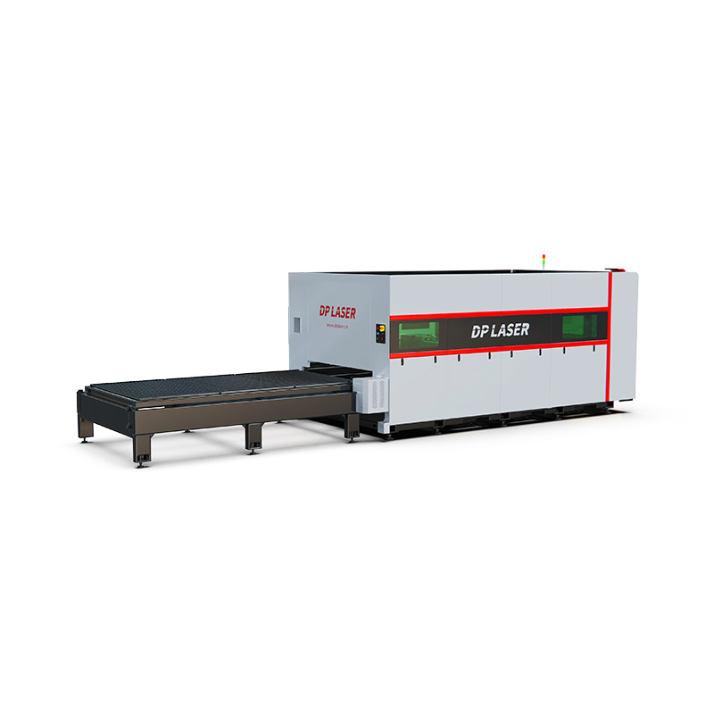
Hardware quality directly dictates production capacity. You cannot achieve tight tolerances with subpar mechanical components. Each major module plays a distinct role in securing precision and maximizing material throughput.
The laser source acts as the heart of the system. Leading manufacturers include IPG, Raycus, and MaxPhotonics. The source dictates the ultimate energy output of the entire machine. A higher kilowatt (kW) rating directly unlocks faster travel speeds on thin-walled materials. It also provides the raw thermal energy needed to cleanly sever thicker pipes. Selecting the right power rating ensures you balance speed against cut quality.
Chucks serve as the primary material handling mechanism during the cut. You must evaluate them based on grip strength, weight capacity, and minimum tailing waste. Full-stroke pneumatic chucks currently lead the industry. They offer exceptional self-centering reliability. This self-centering action is absolutely crucial. It prevents heavy pipe deflection during high-speed rotational sequences.
Pipes are rarely perfectly straight. They often feature slight bows, twists, or irregular surface conditions. The auto-focus cutting head compensates for these material flaws in real-time. It uses advanced capacitive height sensors. These sensors maintain a constant focal length regardless of surface topography. They actively prevent devastating head collisions and ensure edge consistency across the entire cut path.
Software acts as the brain of any modern tube laser cutting machine. Industry-standard platforms like CypTube or Lantek dominate the market. We evaluate them by their ability to optimize complex tool paths seamlessly. Elite software performs common-line cutting. This technique shares a single cut line between two adjacent parts, saving massive amounts of raw material. Furthermore, advanced controllers dynamically compensate for unexpected pipe twist or bowing during execution.
Fiber lasers exhibit incredible versatility across different metals. However, their efficiency varies wildly depending on material composition and profile geometry. You must match your primary material types to the correct machine specifications.
The fiber wavelength interacts beautifully with most industrial metals. The process proves highly effective on carbon steel, stainless steel, aluminum alloys, and brass. The concentrated beam easily vaporizes these dense materials. However, you must exercise caution with highly reflective materials. Copper and certain brass alloys reflect the laser beam backward. This reflection can severely damage internal optics. Processing them safely requires specialized back-reflection protection built into the laser source.
You must frame realistic expectations regarding penetration limits. Wattage directly governs maximum wall thickness. A standard 3kW machine comfortably cuts 8mm carbon steel but completely maxes out at 4mm for aluminum. We recommend evaluating your baseline production needs against the manufacturer's maximum kW ratings. The table below outlines typical thickness capabilities based on common laser power outputs.
| Laser Power (kW) | Max Carbon Steel (mm) | Max Stainless Steel (mm) | Max Aluminum (mm) |
|---|---|---|---|
| 1.5 kW | 6 mm | 3 mm | 2 mm |
| 3.0 kW | 10 mm | 5 mm | 4 mm |
| 6.0 kW | 16 mm | 8 mm | 6 mm |
| 12.0 kW | 25 mm | 12 mm | 10 mm |
Modern tube lasers handle far more than simple round pipes. Standard capabilities easily include round, square, and rectangular tubes. Advanced machine setups push boundaries even further. They process L-shaped angles, C-channels, and complex elliptical profiles. Processing open profiles requires specialized software mapping. You also need distinct chuck jaw adaptations to secure asymmetric shapes safely during rapid rotation.
Acquiring the equipment only solves half the puzzle. Daily operation introduces several physical variables. Managing these variables correctly determines your overall production efficiency and long-term uptime.
Laser cutting relies heavily on high-pressure assist gases. They clear molten material from the kerf and dictate the final edge quality. The ongoing consumption of these gases forms a massive operational reality. You must choose your gas strategy wisely.
| Assist Gas Type | Primary Material Application | Operational Impact & Edge Quality |
|---|---|---|
| Nitrogen (N2) | Stainless Steel, Aluminum | Provides a clean, oxide-free edge. Essential if parts require subsequent welding or powder coating without secondary grinding. High consumption rate. |
| Oxygen (O2) | Thick Carbon Steel | Triggers an exothermic reaction. This adds heat, allowing lower kW lasers to pierce thicker walls. Leaves an oxidized edge requiring cleanup before painting. |
| Compressed Air | Thin Carbon Steel, Aluminum | Massively lowers daily operational expenses. However, it absolutely requires high-quality, oil-free air compressors and rigorous multi-stage filtration. |
Every piece of raw pipe has an uncut section at the end. We call this the tailing. The chucks need physical space to grip the material, preventing the laser from cutting all the way to the absolute edge. This uncut material represents permanent waste. Buyers must evaluate different chuck configurations carefully. Traditional two-chuck systems generate sizable tailing waste. Conversely, modern three-chuck zero-tailing systems grip and shift the pipe independently. This setup drastically shrinks material waste and improves yield per bundle.
High-power lasers demand pristine optical environments. Protective lenses and copper nozzles act as standard consumables. You will replace them regularly. Failing to maintain a perfectly clean environment during lens swaps invites contamination. Even microscopic dust on a protective lens absorbs laser heat. This causes the lens to shatter inside the cutting head. Such failures lead to expensive part replacements and frustrating unplanned downtime.
You cannot simply place a traditional bandsaw operator in front of a CNC laser and expect instant results. Transitioning to a tube fiber laser requires dedicated CAD/CAM proficiency. Operators must understand kerf width compensation, lead-in parameters, and micro-joint placement. Do not underestimate the training period required to master advanced nesting software.
The marketplace offers dozens of brands with overlapping specifications. Filtering through the noise requires a disciplined, data-driven approach. Focus heavily on actual production capability rather than theoretical marketing numbers.
Processing metal pipes with modern fiber technology fundamentally changes fabrication dynamics. It relies on the seamless integration of raw optical power, precise rotational kinematics, and highly intelligent nesting software. Transitioning away from manual cutting tools requires upfront capital, but the massive gains in throughput and precision justify the leap.
Treat this procurement not just as a standalone machine purchase, but as a comprehensive workflow upgrade. We encourage you to take the next step actively. Schedule a technical consultation with an applications engineer, request a custom time-study for your specific parts, or download a comprehensive buyer's specification checklist today.
A: It depends directly on the wattage (kW) and material. A standard 3kW laser cuts up to 10mm carbon steel and 5mm stainless, while a 6kW or higher unit can push past 16mm carbon steel.
A: Standard 2-chuck models are generally limited to enclosed tubes and simple open profiles like angles and channels. Processing heavy structural H or I-beams requires specialized heavy-duty 3D structural laser machines.
A: Traditional 2-chuck systems may leave 150mm to 200mm of tailing. Advanced machines with multi-chuck (3 or 4 chucks) configurations can achieve "zero tailing" (under 50mm), significantly reducing material waste.
A: While Nitrogen and Oxygen are industry standards for specific materials, many fabricators utilize high-pressure, purified compressed air for cutting thinner carbon steel and aluminum to lower operational costs.


